
LGS / 3D

Layers and connections

Explore how steel framing, insulation and linings form a wall, floor and roof. Each layer has a specific role.

These diagrams explain assembly principles. Thicknesses, connections, member spacing and performance are project-specific. They are not construction drawings.

LGS / 01

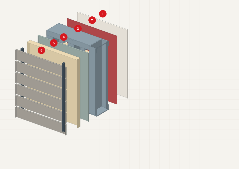
External wall with a ventilated façade

A wall with continuous insulation outside the framing. Service voids, boards and vapour-control position are coordinated through design.

External wall with a ventilated façade — Three-dimensional assembly diagram
From inside to outside

Select a layer to read its role

1Internal lining

Boards form the room finish and contribute to fire and acoustic protection. Type, layers and fixings follow the selected system.

2Airtightness and vapour control

A continuous layer with sealed joints and penetrations limits air leakage. Vapour resistance and its position follow moisture analysis.

3LGS frame and infill

Open C-studs sit in U-tracks. Cavity insulation contributes to heat and sound control; bracing is omitted from this layer diagram.

4External sheathing

A specified board closes the frame. Joint treatment, weather exposure and any structural contribution depend on the selected system.

5Continuous external insulation

Insulation covers the studs to reduce thermal bridging. Thickness, fixings and fire characteristics are designed together.

6Ventilated cavity and cladding

A support system separates cladding from insulation. Drainage, ventilation openings, insect protection and required cavity barriers need detailed coordination.

LGS / 02

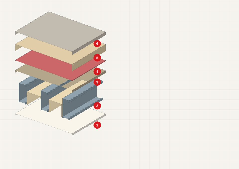
Lightweight intermediate floor

An example of a dry floor. Load transfer, vibration and acoustics are checked together.

Lightweight intermediate floor — Three-dimensional assembly diagram
From bottom to top

Select a layer to read its role

1Ceiling lining

Lower boards close the structure. Hangers and board layers follow fire and acoustic requirements.

2LGS joists and infill

Engineered open sections carry the floor. Cavity insulation helps absorb sound; lateral restraint and supports need separate detailing.

3Structural floor deck

The deck transfers loads to joists. Its joints and fixings must match its designed role.

4Resilient acoustic layer

Limits direct impact-sound transfer. Perimeter isolation prevents rigid sound bridges.

5Dry floor elements

Distribute loads above the resilient layer. Selection depends on use and imposed loads.

6Floor finish

Timber, tiles or other finishes must suit the substrate. Wet areas need additional waterproofing and sealed penetrations.

LGS / 03

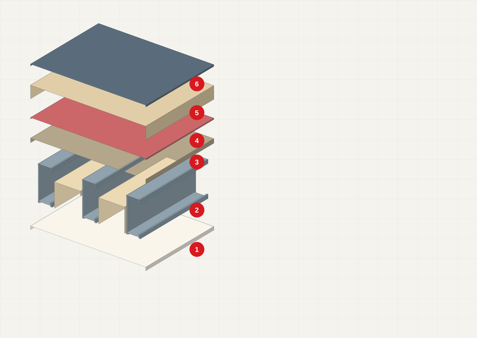
Warm flat roof

A flat roof has a designed fall to drainage. This exploded diagram omits falls and outlets.

Warm flat roof — Three-dimensional assembly diagram
From bottom to top

Select a layer to read its role

1Internal ceiling lining

Closes the space below the roof. Services and fire protection are coordinated with the structure.

2LGS roof members

Sections or trusses transfer roof loads to walls. Infill and insulation positions require thermal and moisture assessment.

3Structural roof deck

Supports the roof package. The selected system must suit loads and fixing requirements.

4Air and vapour control

A sealed layer connects to the corresponding wall layer. Penetrations require planned details.

5Thermal insulation

A continuous layer above the structure reduces thermal bridges. Falls may be formed in the structure or suitable tapered insulation.

6Waterproofing system

Membrane, edges, parapets, outlets and emergency overflows work together. Drainage needs to remain accessible for maintenance.

LGS / 04

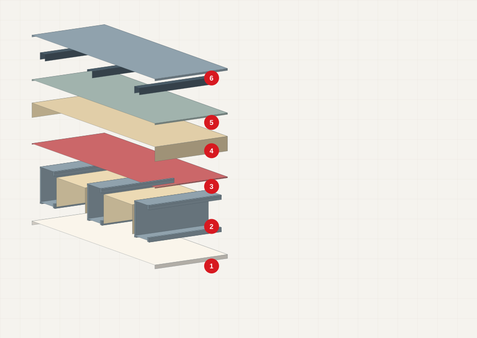
Single-pitch roof

One clear sloping plane. A dual-pitch roof has two coordinated planes and a designed ridge connection.

Single-pitch roof — Three-dimensional assembly diagram
From bottom to top

Select a layer to read its role

1Internal lining

Boards close the room and provide the protective layers required by the design.

2LGS rafters or beams with infill

Engineered sections carry the roof. Supports, lateral restraint and bracing depend on the span and loads.

3Air and vapour control

A continuous layer at the designed location connects to walls and penetrations.

4Continuous insulation

Reduces interruptions at structural members. Cavity and external insulation are assessed as one assembly.

5Secondary water protection

The specified underlay directs incidental water towards the eaves. Laps and penetrations follow system instructions.

6Substructure and roof covering

Ventilated space, battens or profiles and the covering are selected together. Roof slope must suit the chosen covering.

Three important connections

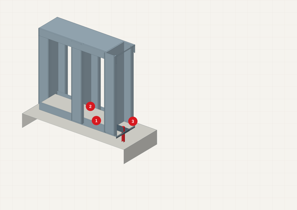
Wall to foundation

Wall to foundation

The substrate (1), moisture separation and bottom U-track (2), and anchorage/hold-down (3) connect the panel to its foundation. Levelling, anchor edge distances and base protection need individual design. Anchor type and number require calculation.
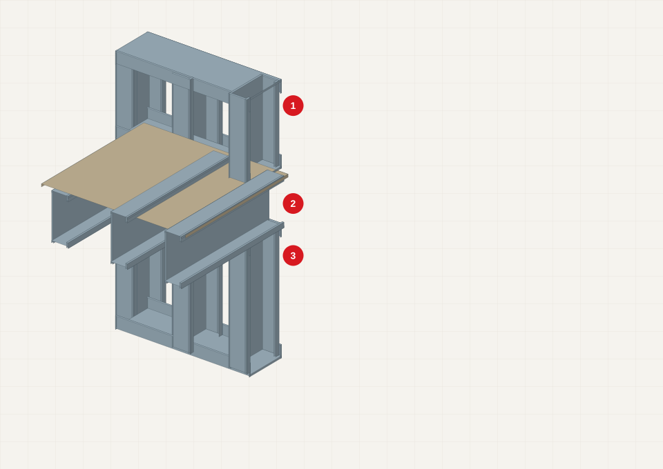
Load transfer at a floor

Load transfer at a floor

The upper wall (1), floor members and edge assembly (2), and lower wall (3) need a clear load path. Bearing, restraint, web reinforcement and acoustic separation depend on the chosen system.

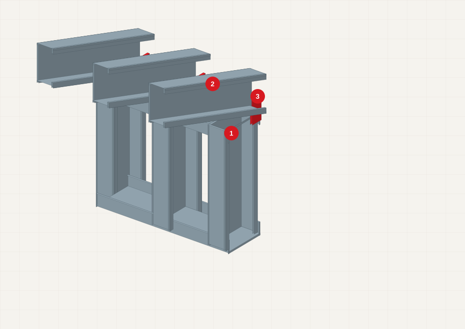
Roof to wall

Roof to wall

The wall head (1), roof members (2) and connectors (3) transfer compression and wind uplift. Screw arrangements, member restraint and thermal-envelope continuity must be coordinated.

Technical references

TOROFORTH

Let’s talk about your space.

Send us the model you like, the location and your main requirements. Together we define the next steps and the scope of a quotation.

Request a price